Breadboard Prototyping: Your Foundation for Electronic Circuits
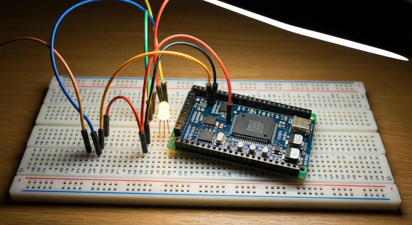
The journey into electronics, whether for hobbyists, students, or professional engineers, almost always begins with a breadboard. This unassuming plastic block with a grid of holes is the unsung hero of countless projects, providing a quick, flexible, and non-destructive way to build and test electronic circuits. Before you ever pick up a soldering iron or design a custom printed circuit board (PCB), the breadboard allows you to bring your ideas to life, test theories, and troubleshoot designs with ease. It’s an indispensable tool for learning, experimenting, and refining your electronic creations.
This comprehensive guide will walk you through everything you need to know about breadboard prototyping. We’ll explore its internal structure, explain how to translate a schematic into a physical layout, guide you through building your very first circuit, discuss common pitfalls, and help you understand when it’s time to move beyond the breadboard.
The Internal World of a Breadboard: How It’s Wired
To effectively use a breadboard, you must first understand its hidden electrical connections. While it appears to be a simple grid of holes, it’s meticulously designed for efficient circuit building.
Terminal Strips (The Main Grid)
At the heart of every breadboard are the “terminal strips,” which form the main grid where most of your components will reside. These are typically divided into two sections, often labeled A-E and F-J, separated by a central channel or “gap.”
- Vertical Connectivity: Within each column (e.g., column 1, 2, 3, etc.), the five holes in a single row (e.g., 1a, 1b, 1c, 1d, 1e) are electrically connected. This means if you insert a component lead into 1a, it will be connected to anything inserted into 1b, 1c, 1d, or 1e. However, 1e is not connected to 2a. The connection runs vertically within each group of five.
- The Center Gap (DIP IC Channel): The crucial gap running down the middle of the breadboard serves a vital purpose: accommodating Dual In-line Package (DIP) integrated circuits (ICs). ICs have pins on both sides. By placing an IC across this gap, its pins on one side (e.g., A-E) are kept electrically isolated from the pins on the other side (F-J), preventing short circuits between opposing pins. This allows you to connect wires or other components to individual IC pins without interference.
Power Rails (The Sides)
Flanking the main terminal strips on either side are the “power rails.” These are typically marked with a red line for positive voltage (+) and a blue or black line for ground (-).
- Horizontal Connectivity: Unlike the vertical connections of the terminal strips, the holes in the power rails are connected horizontally along the entire length of the breadboard. This means all holes in the red-marked strip are connected to each other, forming a continuous positive voltage line. Similarly, all holes in the blue/black-marked strip are connected, forming a continuous ground line.
- Purpose: Power rails are designed to distribute power (voltage and ground) efficiently to all parts of your circuit. Instead of running individual power wires to every component, you can connect your power supply once to the rails and then tap into them as needed throughout your circuit. It’s common practice to connect the positive output of your power supply to the red rail and the negative/ground output to the blue/black rail.
Sizes and Interconnection
Breadboards come in various sizes, often measured by the number of “tie points” (individual holes). Common sizes range from mini breadboards (170 tie points) to full-size ones (830 tie points) and even larger. Larger breadboards are often constructed by linking several smaller breadboard modules together, sometimes with detachable power rails. This modularity allows for flexibility in scaling your prototyping space. Understanding these internal connections is the first and most critical step to successful breadboard prototyping.
Why Choose a Breadboard for Prototyping?
The breadboard’s popularity isn’t just a historical accident; it offers compelling advantages for anyone working with electronics:
- Speed and Ease of Assembly: You can quickly insert components and jumper wires without any soldering. This allows for rapid iteration of designs.
- Flexibility and Reusability: Circuits can be modified or completely reconfigured in minutes. Components are not permanently attached, meaning they can be reused in countless other projects.
- Non-Destructive: There’s no heat involved, so components are safe from potential damage during assembly, unlike soldering.
- Ideal for Learning: Beginners can experiment and make mistakes without fear of permanent damage or wasting expensive components. It provides a hands-on way to visualize and understand circuit behavior.
- Troubleshooting Simplicity: With easily accessible connections, testing voltages and continuity with a multimeter is straightforward. You can isolate sections of a circuit or swap components quickly to diagnose issues.
- Cost-Effective: Breadboards themselves are inexpensive, and the ability to reuse components saves money in the long run, especially during the experimental phase.
Essential Gear for Your Breadboarding Journey
Before you start building, gather these fundamental tools and components:
- The Breadboard: Choose a size appropriate for your expected projects. An 830-tie point breadboard is a great all-rounder.
- Jumper Wires: These are crucial for making connections.
- Solid Core Wires: Ideal for breadboards as their rigid ends fit snugly into the holes and maintain connections. A kit with various pre-cut lengths is highly recommended.
- Flexible Wires (Male-Male, Male-Female, Female-Female): Useful for connecting to development boards (like an ESP32) or external modules.
- Power Supply:
- Bench Power Supply: Offers adjustable voltage and current, essential for serious prototyping.
- Dedicated Breadboard Power Module: These small boards often plug directly into the breadboard’s power rails and can provide common voltages (e.g., 3.3V and 5V) from a USB or DC barrel jack input.
- Battery Packs: Simple and portable for low-power circuits (e.g., AA/AAA battery holders).
- Microcontroller Boards: Many development boards like the ESP32 or Arduino provide 3.3V or 5V outputs that can power small breadboard circuits. More on leveraging these later.
- Multimeter: Absolutely essential for checking voltage, current, and continuity. It’s your primary troubleshooting tool.
- Wire Strippers/Cutters: For preparing your own solid core wires if you don’t use pre-cut jumpers.
- Basic Components:
- Resistors: A variety pack is invaluable for current limiting, voltage division, etc.
- LEDs: For visual indicators.
- Capacitors: Electrolytic and ceramic, for smoothing power, timing, etc.
- Diodes: Rectification, protection.
- Transistors: Switching, amplification.
- Integrated Circuits (ICs): Microcontrollers, logic gates, op-amps, etc.
- Switches/Buttons: For user input.
From Schematic to Breadboard: Planning Your Layout
Translating an abstract schematic diagram into a tangible breadboard layout is a skill that improves with practice. A well-planned layout saves time, reduces errors, and makes troubleshooting much easier.
Understanding Schematics
A schematic is a symbolic representation of a circuit. Each component has a standard symbol, and lines represent electrical connections. Before you touch a breadboard, take time to understand:
- Component Identification: Recognize all the symbols (resistors, capacitors, LEDs, ICs, power sources).
- Connection Points: Trace the paths of current flow and identify which pins/leads of components connect to which others.
- Polarity: Note any components that require specific orientation (LEDs, diodes, electrolytic capacitors, ICs).
Mental Mapping and Physical Placement
You need to mentally (or physically) map the schematic onto the breadboard’s grid.
- Start with Power: Connect your power supply to the breadboard’s power rails. Use red for positive (+) and blue/black for ground (-). This establishes a clear power distribution network.
- Place Key Components: Position the largest or most central components first, especially ICs, placing them across the center gap. This acts as an anchor for the rest of your circuit.
- Group Related Components: Try to keep components that are closely connected in the schematic physically close together on the breadboard. This minimizes wire lengths and reduces clutter.
Strategic Component Arrangement
- Minimize Wire Lengths: Use the shortest possible jumper wires to connect components. Long, sprawling wires are prone to tangles, accidental disconnections, and can introduce noise into sensitive circuits.
- Avoid “Wire Spaghetti”: While sometimes unavoidable in complex circuits, strive for neatness. Run wires parallel to each other where possible.
- Consider Component Orientation: For polarized components (LEDs, diodes, electrolytic capacitors, ICs), ensure they are inserted in the correct direction as indicated by the schematic or component markings. Reversed polarity can prevent the circuit from working or even damage components.
- Use Color-Coding for Wires: Establish a consistent color scheme for your jumper wires. For example:
- Red: Positive voltage (VCC)
- Blue/Black: Ground (GND)
- Yellow/Orange: Signal lines
- Green/White: Data lines This makes it much easier to trace connections and troubleshoot.
By planning your layout methodically, you transform a potentially messy tangle into an organized, readable circuit that’s a joy to work with.
Your First Circuit: Lighting an LED
Let’s build a classic beginner circuit: lighting an LED (Light Emitting Diode) with a current-limiting resistor. This simple project demonstrates fundamental breadboarding techniques and the importance of resistance.
The Goal: Safely illuminate a standard 5mm LED using a 5V power supply.
Components Needed:
- Breadboard
- 5V DC power supply (e.g., a breadboard power module, a battery pack, or 5V from an ESP32 or Arduino board)
- 1x LED (any color)
- 1x Resistor (220 Ohm to 1k Ohm is a good starting range for 5V, a 330 Ohm is common)
- 2-3x Jumper Wires
Understanding the LED and Resistor:
- LED Polarity: LEDs are diodes, meaning current flows in one direction. They have two leads:
- Anode (+): The longer lead, connects to the positive side of the power supply.
- Cathode (-): The shorter lead, connects to the negative (ground) side.
- Tip: The flat edge on the plastic casing of a round LED also indicates the cathode side.
- Current-Limiting Resistor: An LED has a specific “forward voltage” (Vf) and “forward current” (If) it requires to operate correctly. If you connect an LED directly to a 5V supply without a resistor, too much current will flow, burning out the LED almost instantly. The resistor limits the current, protecting the LED.
Calculating Resistor Value (Optional but good to know):
Using Ohm’s Law (V = IR), we can determine a suitable resistor.
- Assume your LED has a forward voltage (Vf) of approximately 2V (this varies by color, e.g., red ~1.8V, blue/white ~3.2V).
- Assume you want a forward current (If) of 20mA (0.02A) for brightness.
- Your supply voltage (Vs) is 5V.
The voltage drop across the resistor (Vr) will be: Vr = Vs - Vf = 5V - 2V = 3V.
Now, calculate the resistance (R): R = Vr / If = 3V / 0.02A = 150 Ohms.
A 150 Ohm resistor would be ideal. Since a 150 Ohm might not be readily available, a 220 Ohm or 330 Ohm resistor will also work safely, making the LED slightly dimmer but still perfectly visible. Let’s use a 330 Ohm resistor for this example, a common value.
Step-by-Step Build:
- Prepare Power: Connect your 5V power supply to the breadboard’s power rails. Connect the positive (+) output to the red rail and the negative (-) or ground output to the blue/black rail. If using an ESP32, connect its 5V pin to the red rail and its GND pin to the blue/black rail. This will distribute power throughout the rails. For more advanced power considerations with microcontrollers, see our guide on
/esp32-home-automation-projects/. - Place the LED: Carefully insert the LED into the breadboard. Place its longer lead (anode) into a hole in one column (e.g., E10) and its shorter lead (cathode) into a hole in an adjacent column (e.g., E12). Ensure it bridges the center gap if you have space, but for a simple circuit like this, it’s not strictly necessary. The key is that the two leads are in different electrically connected rows of five.
- Place the Resistor: Insert one lead of the 330 Ohm resistor into the same row as the LED’s anode (e.g., A10). Insert the other lead of the resistor into a new row (e.g., A8).
- Connect to Power:
- Use a jumper wire to connect the resistor’s input (e.g., B8) to the positive (+) power rail (red line).
- Use another jumper wire to connect the LED’s cathode (e.g., B12) to the ground (-) power rail (blue/black line).
- Double-Check Connections:
- Resistor connected to positive power rail.
- Resistor output connected to LED anode (+).
- LED cathode (-) connected to ground power rail.
- LED polarity is correct (long lead to positive side of resistor, short lead to ground).
- Apply Power and Test: Turn on your 5V power supply. The LED should light up! If it doesn’t, don’t panic; proceed to the “Common Mistakes” section for troubleshooting.
This simple circuit demonstrates the fundamental building blocks of electronics on a breadboard: power distribution, component placement, and series connections.
Powering Your Breadboard: Getting Voltage Where It Needs to Go
Providing stable and appropriate power is crucial for any breadboard circuit. There are several common methods, each with its advantages.
- Bench Power Supply: This is the most versatile option. A lab-grade bench power supply allows you to precisely set voltage and current limits, protecting your circuit from over-current or over-voltage. You typically connect its positive and negative outputs directly to your breadboard’s power rails using jumper wires.
- Dedicated Breadboard Power Modules: These compact modules are incredibly popular. They usually plug directly into the breadboard’s power rails and take input from a DC barrel jack or a USB port. Many offer selectable 3.3V and 5V outputs, making them convenient for microcontroller-based projects.
- Battery Packs: For portable projects or when you need isolation from mains power, battery packs (e.g., 9V, AA/AAA holders) are a simple solution. Remember to include appropriate voltage regulators (like a 7805 for 5V) if your circuit requires a stable voltage lower than the battery’s output.
- Microcontroller Boards: Development boards such as the ESP32, Arduino Uno, or Raspberry Pi Pico often provide regulated 3.3V and/or 5V pins. For small circuits that don’t draw much current, you can power your breadboard by connecting these pins to your breadboard’s power rails. This is particularly useful when integrating sensors or components directly with your microcontroller projects. For more ideas on leveraging the ESP32’s capabilities, check out our guide on
/esp32-home-automation-projects/.
Safety First: Voltage and Current Considerations
- Polarity: Always double-check your positive and negative connections. Reversing polarity can damage polarized components like LEDs, electrolytic capacitors, and ICs.
- Voltage Limits: Ensure your supply voltage matches the requirements of your components. Exceeding a component’s maximum voltage rating will likely destroy it.
- Current Limits: While breadboards can handle a few amps (typically 1-2A per connection), avoid high-current applications. If your circuit draws significant current, the resistance of the breadboard’s internal connections can cause voltage drops and generate heat, potentially damaging the breadboard or leading to unreliable operation.
Common Breadboarding Mistakes and How to Troubleshoot
Even experienced prototypers make mistakes. Knowing the common pitfalls can help you troubleshoot efficiently.
- Power Rail Mix-ups: This is perhaps the most frequent error.
- Confusing positive and negative: Accidentally connecting a component’s positive lead to ground or vice-versa. Always trace your power lines.
- Using only one set of rails: Many breadboards have two sets of power rails on opposing sides. Beginners sometimes only connect power to one side, forgetting to bridge it to the other side if needed, or failing to connect all necessary components to the powered rails.
- Multiple voltage rails: If your circuit uses 3.3V and 5V, ensure these different voltage rails are clearly separated and don’t short together.
- Loose Connections: Wires or component leads not fully inserted into the breadboard holes. This causes intermittent or no contact. Gently push all connections firmly into place. If using old, bent, or thin-gauge wires, they might not make good contact.
- Incorrect Component Orientation:
- LEDs/Diodes: Reversed anode/cathode.
- Electrolytic Capacitors: Reversed positive/negative.
- Integrated Circuits (ICs): Pin 1 (often marked with a dot or notch) must be correctly oriented.
- Always refer to datasheets or component markings.
- Short Circuits:
- Adjacent leads touching: Component leads that are too close together can accidentally short.
- Wire insulation stripped too long: Exposing too much bare wire can lead to accidental contact.
- Incorrect wire placement: Wires touching where they shouldn’t.
- Use a multimeter in continuity mode to check for unintended shorts.
- Component Damage:
- Over-voltage/current: Applying too much voltage or failing to use current-limiting resistors (as with LEDs).
- Static Discharge: Handle sensitive ICs with care, especially in dry environments.
- “Wire Spaghetti” Syndrome: A tangled mess of wires makes it nearly impossible to trace connections, identify errors, or make modifications. This is why planning your layout and using appropriately sized, color-coded wires is so important.
Troubleshooting Steps:
- Check Power: Is the power supply on? Is it providing the correct voltage? Are the power rails actually connected to the supply?
- Check Ground: Ensure all components that need to be grounded are actually connected to the ground rail.
- Check All Connections: Visually inspect every wire and component. Are they firmly seated? Is anything obviously misplaced?
- Check Polarity: Verify the orientation of all polarized components.
- Use Your Multimeter:
- Voltage Mode: Check voltage at various points (e.g., across the LED, across the resistor, at IC pins).
- Continuity Mode: Check for unintended shorts or open circuits where there should be connections.
- Simplify: If it’s a complex circuit, try to isolate sections. Remove non-essential parts and test the core functionality first.
- Take a Break: Sometimes, stepping away and coming back with fresh eyes helps spot obvious mistakes.
Beyond the Breadboard: When to Solder
The breadboard is an incredible tool for prototyping, but it’s not meant for permanent solutions. There comes a point in every project’s lifecycle when you need to graduate from the breadboard to a more robust and permanent form.
Signs It’s Time to Move On:
- Stability and Reliability: Your prototype works perfectly and consistently on the breadboard, and you’re confident in its design.
- Permanence: You want to build a finished product or a long-term installation that won’t accidentally fall apart or lose connections.
- Robustness: The circuit needs to withstand movement, vibration, or environmental factors that would easily disrupt breadboard connections.
- Size and Form Factor: Breadboards are bulky. For compact devices, wearable tech, or enclosures, a soldered solution is essential.
- High-Frequency/High-Current Applications: Breadboards introduce parasitic capacitance and inductance due to their internal wiring, which can affect high-frequency signals. Their internal resistance also makes them unsuitable for high-current applications.
Transitioning from Breadboard:
Once you’re ready to make your circuit permanent, you have several options:
- Stripboard (Veroboard): Features parallel strips of copper tracks, usually with holes at 0.1-inch intervals. You cut tracks to break connections where needed and solder components. It’s a step up from breadboarding in terms of permanence.
- Perfboard (Prototyping Board): A simpler board with individual pads (holes) that are not connected. You solder components and then create connections by soldering wires or component leads together.
- Custom Printed Circuit Boards (PCBs): For truly professional and compact results, designing a custom PCB is the ultimate step. This involves creating a layout in software, which is then manufactured. This is a more advanced process but offers the best performance, reliability, and aesthetics.
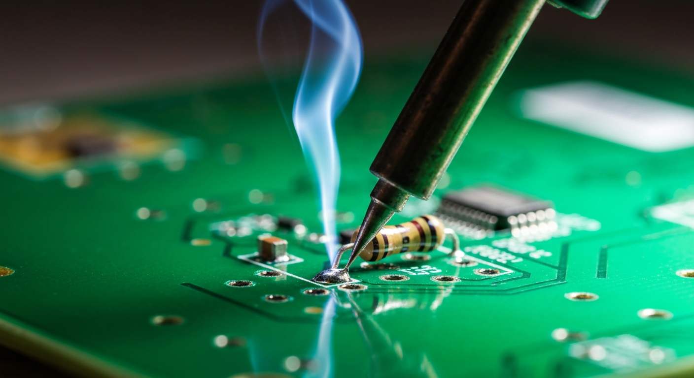
The transition from breadboarding to soldering is a natural progression in electronics. To learn more about the different soldering techniques and when to use them, explore our guide on /through-hole-vs-smd-soldering/.
Conclusion
Breadboard prototyping is more than just connecting wires; it’s a fundamental skill that empowers you to explore, innovate, and bring your electronic ideas to life. From understanding its internal connections to meticulously planning your layouts and carefully troubleshooting, each step builds confidence and expertise. Embrace the flexibility it offers, learn from your mistakes, and use it as your creative canvas. Once your breadboard prototype shines brightly and reliably, you’ll know you’re ready for the next exciting step in your electronics journey.
Frequently Asked Questions
Q1: How do I know if my breadboard is faulty or has bad connections? A1: A common issue with older or cheaper breadboards is loose internal contacts. You can test this with a multimeter in continuity mode. Insert a component lead or a stiff wire into one hole of a connected row (e.g., 1a) and touch the multimeter probe to it. Then, touch the other probe to each of the other four holes in that row (1b, 1c, 1d, 1e). You should hear a beep or see a zero resistance reading for all of them. If you don’t, that row might have a faulty connection. Repeat for power rails.
Q2: Can I use different voltages on the same breadboard simultaneously? A2: Yes, but with extreme caution. You can dedicate different sections of the breadboard’s power rails to different voltages (e.g., one side for 5V, the other for 3.3V). However, you must ensure these separate power rails are never accidentally shorted together, and that components are only connected to their appropriate voltage. Using separate breadboards for distinctly different voltage domains is often a safer approach for beginners.
Q3: What’s the best way to store jumper wires to avoid tangles and make them easy to find? A3: Tangled jumper wires are a common frustration. The best way to store them is organized by length and type. Small tackle boxes or plastic containers with dividers work well. Some people use zip-tie bags or even pegboards with hooks to hang pre-made wire bundles. Keeping them neat saves immense time and frustration during prototyping.
Q4: My circuit worked yesterday, but it’s not working today. What should I check first? A4: This is a classic breadboard problem, often due to its temporary nature. The first things to check are:
- Power: Is the power supply on and connected correctly? Is the battery dead?
- Loose Connections: Wires can easily shift or become loose. Gently press down on all jumper wires and component leads to ensure they’re firmly seated.
- Component Orientation: Double-check polarized components.
- Damaged Component: Rarely, a component might have failed.
- External Factors: Has anything else changed (e.g., a new power supply, a moved wire)?
Q5: Is breadboarding suitable for high-frequency or RF circuits? A5: Generally, no. Breadboards are designed for relatively low-frequency (up to a few MHz) digital and analog circuits. At higher frequencies, the internal capacitance between adjacent strips, the inductance of the long power rails, and the unshielded nature of the connections can introduce significant noise, signal reflections, and unwanted oscillations, making it very difficult to get reliable performance. For RF and high-frequency work, custom PCBs or specialized prototyping techniques are required.